Gm-C integrators for low-power and low voltage applications. A gaussian polyphase filter for mobile transceivers in 0.35
4.4. Low-power luminance video filter. Noise driven power
The fundamental limits have shown the difference between an analogue filter and a digital one when signal to noise ratio and power/pole are taken as variables in the comparison. However, it is not clear for which S/N ratio the transition between an efficient analog filter and a digital filter takes place. According to the previous conclusions, this transition could be somewhere in between 50dB and 60dB which makes difficult to decide whether or not a digital filter is power efficient when compared to an analog filter.
The two integrators presented above are used to realize the video filter from Chapter2 in an analog way and to make a comparison in power with the digital approach. The case of study is a luminance input filter and the reason to take such an example relies on the fact that an 8-bit solution will provide a theoretical S/N of about 50dB. This value is sufficient for video purposes. Moreover, it is important to consider the same technology for all realizations to allow a meaningful comparison.
Matching in this type of filters is not important. Therefore we are dealing with noise driven power consumption. The analogue filter can be realized in different ways: Gm-C, Mosfet-C, Switched-Current, Switched-Capacitors. As we shall see there are extra problems due to the impossibility to open the switches for SC and SI techniques as long as some other techniques like switched-opamp are not employed [14]. Usually, there is a need for a DC-DC up transformer. The extra noise added from undersampling of high frequency white noise into the baseband and the power needed for clocking, makes sampled data filters not adequate for low-power video processing. That is why only Gm-C filters have been considered in this comparison.
4.4.1. Specifications and synthesis
In order to start the comparison, we need to specify the analog prototype. The requirements are presented in Table 4.1. For a luminance video filter it is important to have a very low pass-band ripple. For this reason, the possible solutions are Butterworth and inverse-Chebyshev filters with a maximally flat amplitude in the pass-band.
|
Pass-band edge |
5.5MHz |
|
Stop-band edge |
14.8MHz |
|
Stop-band rejection |
³ 30dB |
|
Group-delay |
46ns£ t gr£ 65ns |
|
THD |
52dB |
|
Technology |
0.5mm CMOS |
Table 4.1: Video filter specís
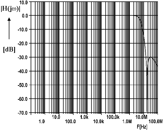
It is known that inverse-Chebyshev filters provide a smaller group-delay when compared to Butterworth counterpart. That is why, an inverse-Chebyshev filter has been chosen. The synthesis procedure is given in Appendix 2 and the outcome is the low-pass prototype illustrated in fig.2.13 from Chapter 2. The frequency transfer from fig.4.12 shows a notch at 16MHz and a stop-band rejection of -30dB. The group-delay of the filter lies somewhere between 46ns and 59ns, thus within the specifications.
4.4.2. The study approach
The leapfrog simulation of ladders is a systematic approach which can be used in the realization of analog filters. The reason for using this method consists in the low sensitivity property of the transfer with respect to the limitations of gain, quality
|
|
|
Fig.4.12: The frequency transfer of the video filter |
|
|
|
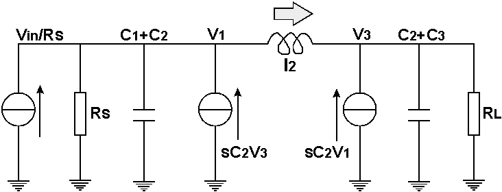
Fig.4.13: The Norton transformation |
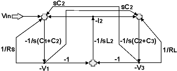
factors and bandwidth in the active elements. In the lowpass prototype we have transmission zeros difficult to simulate actively. That is why a Norton transformation is needed as depicted in fig.4.13. The signal flow graph follows according to the prototype from fig.4.13 is shown in fig.4.14.
|
|
|
Fig.4.14: The SFG of the filter |
4.4.3. The current Gm-C approach
In this approach, we are using current Gm-C integrators from fig.4.9. The integrators have equal unity transconductances gm and different capacitors. The realization of the filter is shown in fig.4.15. In the signal flow graph the summing nodes are current summing nodes while the state variables -V1 and -V2 are voltages. The state variables in this appr


